Introduction
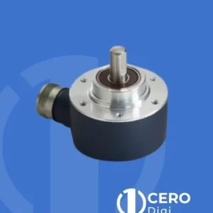
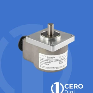
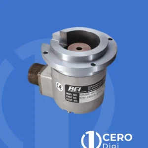
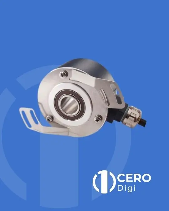
BEI Sensors DHO5S Series High Temperature Encoders are specially designed for hoisting motor applications. Built from a solid and reliable mechanical and electrical platform, the series delivers outstanding robustness, long service life, and high performance across extreme temperatures (–30°C to +120°C).
Features
BEI Sensors DHO5S Series High Temperature Encoders Incremental Encoders:
• Through hollow shaft version Ø14mm
• Robustness and excellent resistance to shocks/vibrations ‘’long life system’’
• High protection level IP65
• Electronics: 5Vdc – RS422 – TTL circuits
• High performances in temperature –30°C to 120°C
• Resolution: 1024 ppr
• Connection: cable output with M23 connector
• Easy mounting thanks to the adapted DAC (Anti-Coupling Device)
• High performance in frequency of output signals: 300 kHz
Mechanical Specifications
| Parameter | Value |
| Material – Cover | Zinc alloy |
| Material – Body | Aluminum |
| Material – Shaft | Stainless steel |
| Bearings | Sealed ball bearings with high temperature grease |
| Max Load – Axial | 20 N |
| Max Load – Radial | 50 N |
| Shaft Inertia | ≤ 2.2×10⁻⁶ kg·m² |
| Torque | ≤ 6×10⁻³ N·m |
| Protection (EN 60529) | IP 65 |
| Permissible Max. Speed | 6 000 min⁻¹ |
| Continuous Max. Speed | 4 000 min⁻¹ |
| Shocks (EN 60068-2-27) | ≤ 2 000 m·s⁻² (during 6 ms) |
| Vibrations (EN 60068-2-6) | ≤ 100 m·s⁻² (55…2 000 Hz) |
| EMC | EN 50081-1, EN 61000-6-2 |
| Isolation | 1 000 V eff |
| Encoder Weight (Approx.) | 0.500 kg |
| Operating Temperature | –30°C to +120°C (encoder surface temperature) |
| Storage Temperature | –40°C to +100°C |
| Torque (ring pressure screw) | 0.7…0.9 N·m |
Output Signals
Signals A, B, 0
The channel B (mounting front) arrives before A, clockwise seen from the bearings housing – DAC side.
Period : 360° – Cycle ratio : 180°
The shift between each front is given by the formula a > 135/F (a in time in microseconds, F frequency in kHz, ex: 100kHz, a > 1,35μs)
The 90° electrical phase-shift between A and B signals determines the rotation direction:
• clockwise (seen from DAC side) during the mounting front of A, B signal is ‘’1’’,
• counter-clockwise, during mounting, the front of A and B channels is ‘’0’’.
Digital Output Signals – Electrical Specifications
| Parameter | Value |
| Electronics Version | 2G2 – 150 kHz |
| Supply Voltage | 5 Vdc ± 10% |
| Output Type | RS422 / TTL (differential) |
| Current Consumption (no load) | 75 mA max |
| Current per Channel | 40 mA max |
| Logic 0 (Is = 20mA) | Vol = 0.5 Vdc max |
| Logic 1 (Is = 20mA) | Voh = 4 Vdc min |
| Frequency Capability | 300 kHz |
| Resolution | 1024 ppr (standard); see Available Resolutions section |
| Signals | A, A/, B, B/, 0, 0/ (0 gated A & B) |
| Period / Cycle Ratio | 360° / 180° |
| Phase Shift Formula (A–B edge) | a > 135/F (a in µs, F in kHz; e.g. at 100 kHz → a > 1.35 µs) |
Find More Drawings & Technical Specifications … Click Here